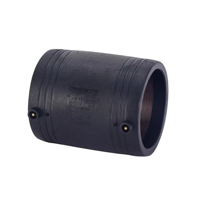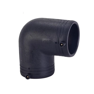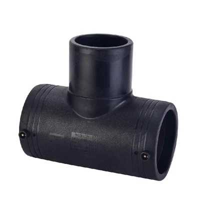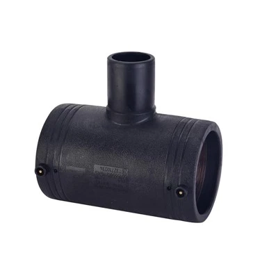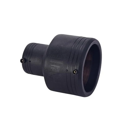
Structural Features of Electrofusion Fittings
Beneath the seemingly symmetrical cylindrical appearance of electrofusion fittings lies a sophisticated design:
Heating Coil Layout: The built-in resistance wires are arranged in a spiral progression to ensure uniform heat conduction during welding.
Limiting Boss: The annular protrusion on the inner side of the port is used to clamp the pipe; it is usually set on one side.
Observation Hole Location: The welding indicator point is often offset to one side for easy monitoring during construction.
Methods for Determining Installation Direction
In actual operation, the direction can be identified through three steps:
Marking Confirmation: Look for arrow markings or color ring markings on the outer wall of the fitting (common) (For gas pipe fittings)
Structural matching: Orient the limiting boss end toward the insertion direction of the pipe to be connected.
Instrument assistance: Use an infrared thermometer to detect the side with higher heating coil density.
Potential effects of reverse installation: Although some fittings allow bidirectional use, special considerations apply in certain scenarios:
Pressure piping systems: Reverse installation may reduce the pressure-bearing capacity of the weld zone by 20%-30%.
Reducing fittings: Reversing the diameter at the reducer will cause increased turbulence and wear.
Branching fittings: Incorrect orientation of tees and crosses will cause an imbalance in the flow distribution ratio.